As with resin selection, plastic part design is critical to successful application. There are design approaches that should be avoided if possible.
| Design Don't | Design Alternative |
|---|---|
| 5-sided box or cup design that can trap air and drag out plating chemicals, impacting plating quality and cost. | Include drain holes or design part to prevent entrapment of air or plating solution. |
| Tight crevices that can trap plating solution. | Eliminate crevices in the design or include drain hole. |
| Small blind holes with aspect ratio > 5:1. Small holes can trap plating solution that later weeps out and can damage the plating. | Utilize through-holes if possible. Note that blind holes can be plugged to prevent plating solution entrapment, but this operation adds cost. |

Automated Heat Staking Inserts
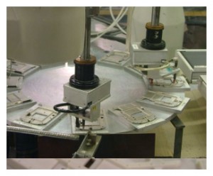
Another issue includes inserts, which can be molded into the part or installed by heat staking or ultrasonic insertion prior to or after plating. If specifying 100 micro-inches (2.5 µm), inserts should be installed prior to plating and masked during the plating operation with a plug or screw to prevent plating on the threads. Standard boss and insert design guidelines should be followed for plated plastic parts with inserts, and brass inserts are compatible with electroless and electroplating plating processes. Photo below shows automated insert installation using heat staking. Ultrasonic insertion is also available.
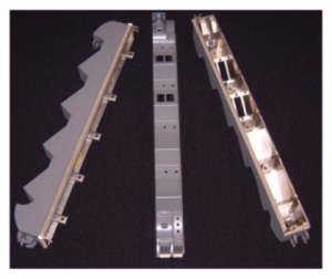
 Conventional finishing operations such gasket installation for environmental or EMI/RFI seal, decorative paint, and part labeling can be used to finish the plated plastic part to final OEM specifications. Material selection for gaskets, decorative paint and label ink are determined by the final plating metal layer on the part. Photo below shows plated plastic faceplate with fabric over foam conductive gaskets, and latches installed and decorative paint.
Specifying the plating system includes the following elements:
- Thickness is usually defined as a minimum. If required due to part function or fit, plating can be specified as a thickness range. Plating thickness is commonly measured using X-ray fluorescence, a non-destructive test with accuracy down to 2x 10⁻⁷ inches (0.005 µm). Note modern X-ray equipment can measure up to 3 unique metal layers o a plated plastic part.
- Where surface conductivity is critical due to application as EMI/RFI shield or ESD coating, the coating resistance should be specified, either in ohms per square or point-to-point ohms resistance. In this case, plating thickness does not need to be specified.
- Plating adhesion is commonly measured according to ASTM D3359 Standard. This standard is based on tape test (either destructive or non-destructive) and 1-5 scale for amount of plating removed during the tape test (5 is no metal removed and 1 is complete removal of the plating).

